
Table of Contents
- What Is Steel Pipe for Directional Drilling?
- Why Steel Pipe Matters in HDD Projects
- HDD Drill Pipe Specifications and Standards
- Directional Drilling Pipe Types and Materials
- Casing Pipe in Directional Drilling Applications
- API Drill Pipe Grades for HDD Operations
- Thrust Force Distribution and Installation Design
- Corrosion Mitigation and Long-Term Durability
- Failure Analysis and Troubleshooting Common Issues
- Regulatory Compliance and Environmental Considerations
Last Updated: July 29, 2026
What Is Steel Pipe for Directional Drilling?
Steel pipe for directional drilling forms the backbone of horizontal directional drilling (HDD) operations, serving as the conduit for drilling fluids and the structural element that withstands tremendous underground pressures. The pipe must resist bending, pulling, and twisting forces while remaining flexible enough to navigate curved bore paths beneath obstacles like highways, rivers, and existing utilities.
Unlike traditional vertical drilling, directional drilling demands steel pipe that balances competing requirements: high tensile strength to handle pullback forces exceeding 500,000 pounds, combined with flexibility to bend through S-curves without cracking. The material must resist corrosion from drilling mud, maintain joint integrity under cyclic stress, and perform reliably in depths ranging from shallow utility crossings to installations exceeding 3,000 feet.
Why Steel Pipe Matters in HDD Projects
A single pullback failure can cost tens of thousands in lost equipment, re-drilling, and schedule delays. Steel pipe selection determines whether your project finishes on time or requires costly mid-bore repairs.
Many contractors mistakenly treat steel pipe as a commodity purchase, specifying the lowest price per foot without considering grade, wall thickness, or manufacturing tolerances. This approach typically backfires. Undersized or lower-grade pipe fails under actual pullback loads, while oversized pipe wastes money and adds unnecessary weight to the rig.
Proper steel pipe specification reduces equipment stress, prevents joint failures that compromise drilling fluid circulation, and ensures predictable performance under calculated loads.
Before selecting steel pipe, calculate your actual pullback force based on bore length, depth, soil friction, and casing diameter. Oversizing by 20% for safety is reasonable; oversizing by 50% wastes money and adds unnecessary rig load.
HDD Drill Pipe Specifications and Standards
Drill pipe for directional drilling must meet specific industry standards that define material properties, dimensional tolerances, and testing requirements. These standards exist because HDD operations expose pipe to extreme conditions that ordinary structural steel cannot withstand.
ASTM and API Requirements
The American Petroleum Institute (API) and American Society for Testing and Materials (ASTM) publish specifications governing drill pipe manufacture. API Spec 7 defines drill pipe grades, wall thickness classes, and connection types. API specifications require that all drill pipe undergo hydrostatic testing before shipment, pressurizing the pipe to 90% of its yield strength to verify it won’t fail under normal operating conditions.
The key standards contractors encounter are API 7-1 (drill pipe), API 5C3 (casing pipe), and ASTM A252 (pile pipe, sometimes used for larger-diameter applications). Each standard specifies minimum tensile strength, yield strength, and elongation requirements.
Tensile Strength and Material Grade Selection
Tensile strength measures how much pulling force the pipe can withstand before permanent deformation occurs. For drill pipe, tensile strength typically ranges from 75,000 pounds per square inch (psi) for lower grades to 135,000 psi for premium alloy steels.
Most standard HDD applications use Grade E or Grade X drill pipe, which offer 75,000-105,000 psi tensile strength. For longer bores, deeper installations, or larger-diameter product pipes, Grade S or Grade N pipe (105,000-135,000 psi tensile strength) becomes necessary.
Using the correct grade for your application reduces total project cost. Oversizing to a higher grade than necessary wastes money, while undersizing risks failure and costs far more in re-work.
Never assume that “stronger is better” when selecting steel pipe grades. A bore design requiring Grade N pipe but using Grade X pipe will likely experience unexpected failures because the rig operator may apply forces exceeding the lower-grade pipe’s capacity. Always match pipe grade to calculated bore loads.
Directional Drilling Pipe Types and Materials
The term "steel pipe for directional drilling" encompasses several distinct product types, each serving different functions within an HDD operation.
Steel vs. Ductile Iron: Comparative Advantages
Steel drill pipe dominates HDD operations because it combines high tensile strength with the flexibility needed for curved bore paths. Ductile iron pipe offers superior corrosion resistance and lower cost in larger diameters, but it lacks the strength and flexibility required for drill pipe applications. Ductile iron is used as product pipe (the final pipeline being installed) rather than drill pipe.
Steel pipe withstands high tensile and torsional stresses of pullback operations without cracking. The material remains relatively uniform in properties, allowing engineers to predict performance with confidence. Steel joints, when properly designed with restrained connections, maintain fluid-tight seals even under cyclic loading.
Ductile iron pipe works well as the product pipe being pulled through the bore, particularly for water mains and gravity-flow applications. However, ductile iron becomes brittle under the impact loads and bending stresses of drilling operations. Using ductile iron as drill pipe leads to catastrophic joint failures.
| Material | Tensile Strength | Flexibility | Corrosion Resistance | Best Use |
|---|---|---|---|---|
| Carbon Steel Drill Pipe | 75,000-105,000 psi | Excellent | Moderate (requires coating) | Drill pipe for most HDD bores |
| Alloy Steel Drill Pipe | 105,000-135,000 psi | Good | Moderate | Long bores, deep installations |
| Ductile Iron Pipe | 60,000 psi | Poor | Excellent | Product pipe only, not drill pipe |
| Casing Pipe (Steel) | 30,000-65,000 psi | Moderate | Moderate | Bore stabilization, product protection |
Alloy Steel and High-Strength Options
Alloy steel drill pipe incorporates elements like chromium, molybdenum, and vanadium to achieve higher strength without excessive weight. S-135 steel, a premium alloy commonly used in oil and gas drilling, has found increasing use in large-diameter HDD projects, offering 135,000 psi tensile strength while maintaining reasonable toughness. The trade-off is cost: S-135 steel costs 40-60% more than standard Grade E pipe.
Intermediate grades like Grade S (105,000 psi) and Grade N (110,000 psi) often represent the best value for challenging bores because they provide adequate strength without premium pricing. The decision to use alloy steel should rest on engineering calculations demonstrating that lower grades cannot safely handle the loads.
Casing Pipe in Directional Drilling Applications
Casing pipe stabilizes the bore wall, prevents collapse, and protects product pipes from soil contact. While drill pipe transmits drilling forces and drilling fluid circulation, casing pipe serves a different function.
Borehole Stability and Annular Space Management
The borehole is the hole drilled through soil. Casing pipe, inserted into this hole, creates an annular space between the pipe outer diameter and the borehole wall. This space must be filled with drilling mud or grout to prevent bore wall collapse and maintain hydrostatic pressure that supports unstable soil layers.
Borehole stability depends on soil type (clay is more unstable than sand), depth, bore angle, and drilling mud properties. In unstable soils, casing becomes mandatory to prevent catastrophic bore wall collapse that can trap equipment.
A typical specification might call for a 6-inch casing pipe in a 7.5-inch borehole, creating a 0.75-inch annular space. This space accommodates casing spacers and allows mud circulation. Undersized annular spaces restrict mud flow and increase friction; oversized gaps complicate mud management.
Proper borehole stability requires casing installation combined with complete annular space mud-filling and hydrostatic pressure management. Skipping or poorly executing any of these steps dramatically increases pullback friction and failure risk.
Restrained Joint Systems and Pipe Integrity
Pipe joints are the weakest points in any pipe assembly. Under extreme HDD pullback forces, standard threaded connections can loosen, leak, or separate. Restrained joint systems solve this problem by mechanically locking the connection so it cannot separate even under extreme tension.
A restrained joint includes a shoulder or mechanical stop that prevents the inner pipe from pulling out of the outer pipe. This design maintains joint integrity even under cyclic loading. Standard API connections can be upgraded to restrained specifications by adding a mechanical stop, typically costing 15-25% more per joint but essential for any HDD application involving significant pullback forces.
Joint integrity also depends on proper maintenance of the connection. Threads must be clean and undamaged. Connection compounds (thread-sealing lubricants) must be applied correctly to ensure watertight seals. Many joint failures occur not because the design is inadequate, but because connections were made carelessly on site.
API Drill Pipe Grades for HDD Operations
API drill pipe grades represent standardized strength levels that allow engineers and contractors to specify pipe with confidence. Each grade has defined minimum properties that manufacturers must meet.
S-135 Steel and Grade Selection Criteria
S-135 steel represents the highest standard API drill pipe grade, offering 135,000 psi minimum tensile strength. This premium material appears in demanding applications: long bores exceeding 3,000 feet, deep installations, or bores through difficult soil conditions that generate high friction.
The selection process begins with bore design calculations. Engineers determine the maximum pullback force the bore will generate, then select a pipe grade with tensile strength exceeding that force by a safety factor (typically 1.5 to 2.0). If calculations show a maximum pullback force of 200,000 pounds and the pipe has a cross-sectional area of 2 square inches, the required tensile strength is 100,000 psi. Applying a 1.5 safety factor suggests Grade S or N pipe would be appropriate.
Contractors sometimes default to the highest available grade, reasoning that "stronger is always better." This approach wastes money. A bore requiring Grade E pipe does not benefit from Grade N pipe; the extra strength provides no value and increases cost unnecessarily.
| Grade | Tensile Strength | Typical Applications | Cost Index |
|---|---|---|---|
| E | 75,000 psi | Short utility crossings, small diameter | 1.0 |
| X | 95,000 psi | Standard utility installations, medium bore lengths | 1.15 |
| S | 105,000 psi | Long bores, difficult soil conditions | 1.35 |
| N | 110,000 psi | Very long bores, deep installations | 1.45 |
| S-135 | 135,000 psi | Extreme conditions, large diameter, maximum depth | 1.75 |
Thrust Force Distribution and Installation Design
Thrust forces represent the total pulling force applied to the drill string and product pipe during pullback. These forces must be distributed evenly across the pipe cross-section to prevent localized failures or deformation.
The HDD rig’s thrust block transfers pulling force from the hydraulic system to the pipe string. A poorly designed thrust block concentrates force on a small area, creating stress concentrations that can cause local buckling or cracking. Modern HDD rigs use load-spreading collars or saddle blocks that distribute thrust force across a larger pipe section, reducing peak stress.
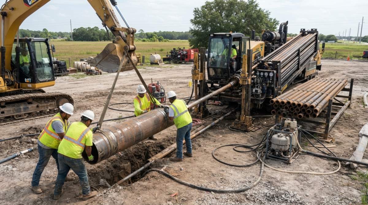
Installation design must account for bore path geometry. A straight bore path generates steady, predictable pullback forces. A bore with multiple curves generates variable forces as the pipe navigates each curve. Proper design accounts for these variations and ensures the selected pipe grade can handle peak forces at the most challenging sections.
Corrosion Mitigation and Long-Term Durability
Steel pipe corrodes when exposed to moisture and oxygen. In HDD applications, the exterior surface contacts soil moisture while the interior contacts drilling mud. Without protection, carbon steel pipe can lose 0.05-0.1 inches of wall thickness per year in corrosive soil conditions.
Corrosion mitigation strategies include external coating (epoxy or polyurethane), internal coating (for product pipes that will carry corrosive fluids), and material selection (higher-chromium alloys resist corrosion better than plain carbon steel). External epoxy coating costs $2-4 per foot and extends pipe life by 15-20 years in typical soil conditions. For permanent installations where the pipe remains in the ground, this coating investment typically pays for itself through extended service life.
Internal coating becomes important when the product pipe will carry corrosive fluids or when water quality is poor. Uncoated steel pipe in these applications can perforate within 5-10 years. Epoxy or polyurethane internal coatings extend service life to 30+ years.
Failure Analysis and Troubleshooting Common Issues
Even with proper specification and installation, failures occur. Understanding failure modes helps contractors recognize problems early and take corrective action.
Pipe Deflection and Joint Integrity Concerns
Pipe deflection occurs when the pipe bends more than its design allows, causing permanent deformation or cracking. This typically happens when the bore path is tighter than anticipated or when the rig operator applies excessive side loads trying to steer the bore.
Visible signs of deflection include bent sections of pipe, flattened areas on the pipe exterior, or visible cracks. Deflection reduces the pipe’s cross-sectional area, increasing stress at that location and triggering joint failure. A deflected section should be cut out and replaced rather than straightened.
Joint separation occurs when the mechanical connection between pipe sections loosens or fails. Causes include improper make-up, corrosion of connection surfaces, or loads exceeding the joint’s capacity. Signs include drilling fluid leaking from the joint, loss of drilling pressure, or visible gaps between connected sections.
Prevention focuses on proper connection make-up procedures, regular inspection of joints for corrosion or damage, and using restrained joint systems for any bore involving significant pullback forces.
Fluid Loss Prevention and Drilling Mud Compatibility
Drilling mud circulates through the pipe interior to carry drill cuttings out of the bore and maintain hydrostatic pressure that stabilizes the bore wall. When pipe joints leak, mud is lost, hydrostatic pressure drops, and bore wall collapse becomes likely.
Fluid loss from pipe joints typically indicates corrosion of connection surfaces or improper make-up. Connection compounds prevent corrosion by creating a barrier between steel surfaces and the corrosive drilling mud environment. Applying the correct compound during make-up is essential.
Drilling mud chemistry affects corrosion rates. Freshwater-based muds are less corrosive than saltwater-based muds. For long bores or bores through corrosive soil, specifying a mud chemistry that minimizes corrosion reduces joint failure risk.
A single leaking joint can cause catastrophic bore wall collapse if not detected and repaired quickly. Establish procedures for monitoring drilling pressure and mud returns. Any unexplained pressure drop or change in mud return volume should trigger immediate investigation of pipe joints and connections.
Regulatory Compliance and Environmental Considerations
HDD projects operate under federal and state regulations governing environmental protection, worker safety, and utility locating. Steel pipe specification must account for these regulatory requirements.
The Occupational Safety and Health Administration (OSHA) establishes standards for underground construction, including requirements for trench support and equipment operation. While HDD is a trenchless technology that minimizes excavation, the bore entry and exit points still require proper shoring and safety measures.
The Environmental Protection Agency (EPA) regulates discharge of drilling fluids and cuttings. Steel pipe selection can reduce environmental impact by minimizing fluid loss, which reduces the volume of mud requiring disposal. Coated pipe that prevents corrosion reduces the need for corrosion-inhibiting additives in drilling mud.
The Utility Locating and Notification Center (commonly called "Call Before You Dig") requires notification before any underground work begins. HDD operators must verify the locations of existing utilities to avoid strikes that could damage existing infrastructure or create safety hazards.
Steel pipe for directional drilling represents a specialized category of materials that demands precise specification and careful installation. The difference between a successful bore and a costly failure often comes down to selecting the right grade, wall thickness, and joint system for your specific bore design. Steel & Pipe Supply works with contractors and engineers to specify steel pipe that matches their actual project requirements, not generic recommendations that may or may not suit the application. Call for a free quote and let our team help you right-size your next HDD project.
Frequently Asked Questions
What types of steel pipe are used in directional drilling?
Steel pipe for directional drilling primarily includes drill pipe, casing pipe, and carrier pipe. Drill pipe transfers torque and pullback force during boring operations, typically made from high-strength alloy steel grades like S-135. Casing pipe protects the borehole and prevents fluid loss, often fabricated from ductile iron or carbon steel. Carrier pipe serves as the final product line installed through the bore. Material selection depends on soil conditions, borehole diameter, tensile strength requirements, and project-specific ASTM or API specifications.
How do HDD drill pipe specifications differ from standard industrial pipe?
HDD drill pipe specifications are engineered for extreme stress conditions including high pullback forces, rotational torque, and pressure cycling. They must meet API or ASTM standards for tensile strength, wall thickness tolerances, and joint integrity. Standard industrial pipe lacks the precision threading, fatigue resistance, and dimensional consistency required for directional drilling. HDD pipe also requires superior corrosion resistance due to exposure to drilling mud and underground moisture. Specifications define exact grades (S-135 steel, for example), outside diameter, wall thickness, and coupling type to ensure safe, reliable bore path completion.
What is the difference between casing pipe and carrier pipe in directional drilling?
Casing pipe is installed during the HDD process to stabilize the borehole, prevent fluid loss, and protect the bore path from collapse. It remains in the ground after drilling is complete. Carrier pipe is the final product, the utility line (water, gas, telecommunications) that will remain permanently in service. Casing pipe is typically larger diameter, made from ductile iron or carbon steel, and designed for temporary pressure. Carrier pipe is smaller, made from materials suited to the utility (often high-strength steel for gas or water lines), and engineered for long-term operational pressure and environmental durability.
How is steel pipe protected from corrosion in directional drilling applications?
Corrosion mitigation strategies include external coatings (polyethylene or epoxy), internal linings, and material selection (ductile iron or alloy steel grades). Casing spacers maintain annular space between casing and bore wall, allowing protective drilling mud circulation. Post-installation, proper backfill and drainage reduce groundwater contact. For long-term protection, carrier pipe often receives fusion-bonded epoxy (FBE) or polyethylene coatings. Regular inspection protocols and cathodic protection systems (for larger installations) extend service life. Material choice, such as corrosion-resistant alloy steel, adds upfront cost but reduces maintenance and replacement expenses over the project lifecycle.
This article was written using GrandRanker