

Table of Contents
- Understanding Steel Beam Basics: Shapes, Grades, and Properties
- How to Calculate Dead Load vs. Live Load for Your Beam
- Steel Beam Load Calculation Formula: Bending Moment and Shear Force
- Using a Structural Steel Beam Calculator and Design Standards
- Steel Beam Span Table: Quick Sizing Reference
- Step-by-Step: How to Calculate Steel Beam Size Manually
- DIY vs. Professional Engineering: Know Your Limits
- Real-World Installation Constraints and Cost-Optimization Strategies
- Common Mistakes to Avoid When Sizing Steel Beams
- Conclusion: Get the Right Beam Size for Your Project
Last Updated: July 14, 2026
Understanding Steel Beam Basics: Shapes, Grades, and Properties
Understanding how to calculate steel beam size requires grasping the fundamentals of beam shapes, material grades, and their structural properties. The shape of your beam, the steel grade you select, and the material properties all directly influence load-carrying capacity and deflection behavior.
(/beam/): Shapes, Grades, and Properties]
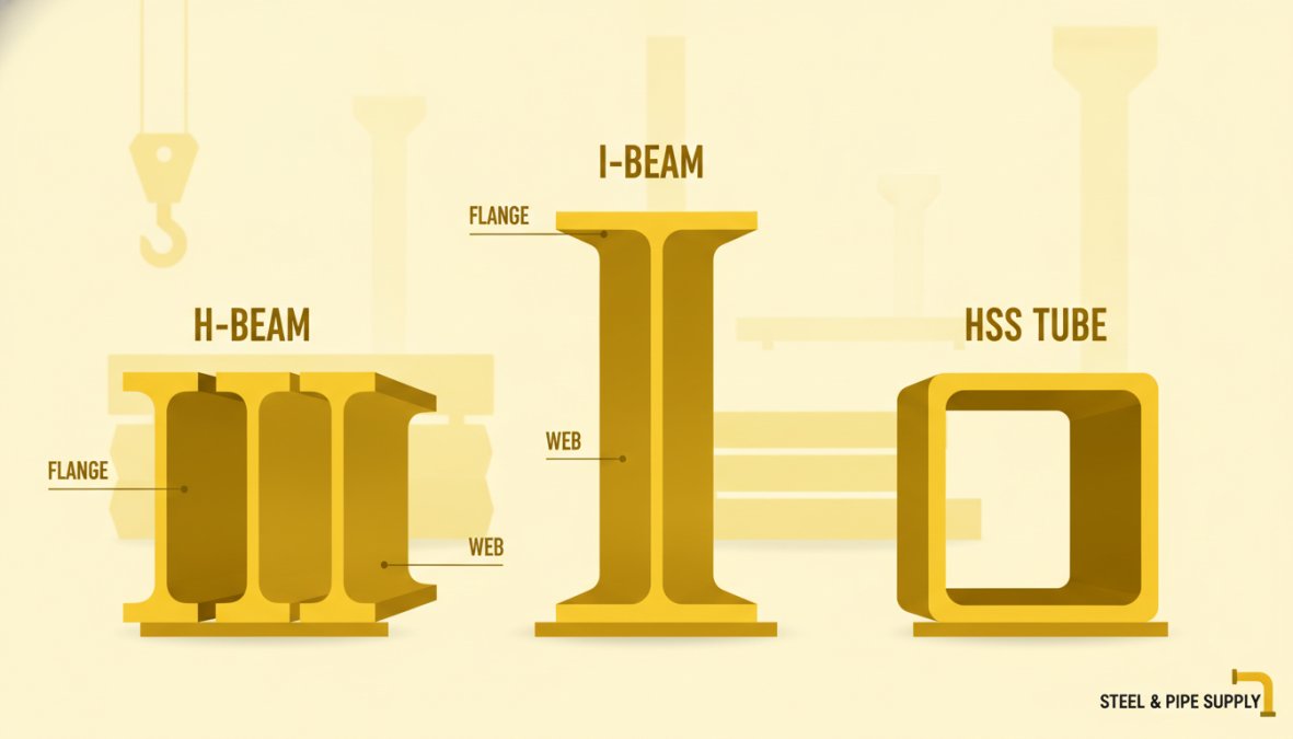
I-Beam vs. H-Beam vs. HSS: Which Shape Do You Need?
An I-beam (wide-flange or W-beam) features a vertical web with two horizontal flanges, resisting bending in one primary direction. An H-beam has more balanced flange dimensions, providing equal strength in both directions. An HSS (hollow structural section) tube offers a closed rectangular or circular profile that distributes loads evenly and provides better torsional resistance.
I-beams excel for floor systems where loads come primarily from above. H-beams work well when you need symmetrical strength. HSS sections shine in applications requiring lateral load resistance or torsion, and they’re easier to protect from corrosion since they lack interior corners where moisture collects.
Beam shape choice isn’t just about load capacity. Installation costs, connection complexity, and local supplier availability often drive the final decision. A contractor might specify an I-beam because local suppliers stock them in every size and connection details are standardized.
Steel Grade and Tensile Strength
Steel grade defines the material’s strength characteristics. Common structural grades include ASTM A36 (36 ksi yield strength), A992 Grade 50 (50 ksi yield), and A588 weathering steel. Yield strength is the stress level at which steel begins to deform permanently. Tensile strength is the maximum stress before breaking.
Higher-grade steel allows smaller, lighter beams for the same load capacity, reducing material and labor costs. However, higher grades cost more per pound. The trade-off between material cost and weight savings determines whether upgrading grades makes financial sense.
A common mistake is assuming higher grade automatically means better performance. Grade selection depends on your specific loads, span length, and deflection limits. A 20-foot residential floor beam might perform identically in A36 or A992; the extra strength adds no value. A 40-foot industrial beam might require A992 to stay within deflection limits, making the upgrade essential.
How to Calculate Dead Load vs. Live Load for Your Beam
Calculating beam size starts with understanding two load categories. Dead load is permanent weight: the beam itself, decking, roofing, and permanently attached equipment. Live load is temporary, movable weight: people, furniture, snow, or wind.
Building codes specify minimum live loads by occupancy. Residential floors typically require 40 psf (pounds per square foot). Commercial offices need 50 psf. Warehouses might require 125 psf or more. Snow loads vary by geographic location; a Minnesota beam must handle significantly more snow than an identical Florida beam.
Dead Load Calculation
Dead load calculation requires identifying every material resting on or attached to your beam, then converting that weight to distributed load across the beam’s length. For a floor beam, this includes the beam itself, floor decking, insulation, ceiling materials, and mechanical systems.
List materials and their unit weights. Steel weighs approximately 490 pounds per cubic foot. Wood decking weighs 2.5 to 4 pounds per square foot. Concrete weighs 150 pounds per cubic foot. Calculate volume or area, multiply by unit weight, then divide by the beam’s span length to get pounds per linear foot (plf).
Example: A 30-foot floor beam supporting a 4-inch concrete slab plus 2 inches of insulation plus mechanical systems. Concrete: 4 inches ÷ 12 = 0.33 feet × 150 psf = 50 psf. Insulation: 2 inches ÷ 12 = 0.167 feet × 1.5 psf = 0.25 psf. Mechanical systems: 10 psf. Total: 60.25 psf. Divided by 30-foot span: 60.25 ÷ 30 = 2 plf from materials, plus the beam’s self-weight (typically 30-50 plf).
Dead load calculation is iterative. Your initial beam size estimate affects self-weight, which affects total dead load, which might require a larger beam. Most engineers start with an estimated beam size, calculate actual dead load including the beam’s weight, then verify the beam is adequate.
Live Load and Snow Load Considerations
Live load represents occupancy-based weight. Building codes define minimums by use: 40 psf for residential, 50 psf for office, 100 psf for storage. These conservative values assume the entire floor is loaded simultaneously.
Snow load varies by latitude, elevation, and local weather patterns. Northern climates might require 50, 75, or 100+ psf. Southern locations might require only 5-10 psf. Check your local building code for the design snow load in your specific location.
Ignoring live load or using values lower than code minimums is the most common sizing error. A beam adequate for dead load alone will fail when temporary loads are applied. Always use code-specified minimums.
Steel Beam Load Calculation Formula: Bending Moment and Shear Force
Once you know your dead and live loads, calculate bending moment and shear force, the internal stresses created when loads act on the beam. Bending moment is the rotational force trying to bend the beam. Shear force is the vertical force trying to slide one section past another.
For a simply supported beam, maximum bending moment occurs at the center and equals (w × L²) ÷ 8, where w is total load per unit length and L is the span. Maximum shear force at the supports equals (w × L) ÷ 2.
Calculating Bending Moment and Section Modulus
The section modulus (S) measures the beam’s cross-section resistance to bending. Higher section modulus means greater bending strength. Required section modulus is: S_required = M ÷ F_b, where M is maximum bending moment and F_b is allowable bending stress.
For ASTM A36 steel using ASD (Allowable Stress Design), allowable bending stress is 24 ksi. For A992 Grade 50, it’s 33 ksi. These values include a safety factor.
Example: A 20-foot beam supporting 500 plf total load. Maximum bending moment = (500 × 20²) ÷ 8 = 25,000 foot-pounds = 300,000 inch-pounds. Using A36 steel with F_b = 24 ksi: S_required = 300,000 ÷ 24,000 = 12.5 cubic inches. A W12×26 I-beam has S = 33.4 cubic inches, which is adequate.
Steel beam tables list section modulus values for standard sizes. Once you calculate S_required, scan the table to find the lightest beam that meets or exceeds that value.
Shear Force Analysis and Deflection Limits
Shear rarely controls beam sizing in typical applications; bending moment usually limits. However, shear becomes critical for short, heavily loaded beams. Shear capacity is checked using formulas that vary by design method.
Deflection is how much the beam bends under load. Building codes limit deflection to prevent safety issues and damage to attached elements. Common limits are L/240 for floors and L/180 for roofs. A 20-foot floor beam should deflect no more than 1 inch under full design load.
Deflection depends on moment of inertia (I), which measures how the cross-section distributes material away from the neutral axis. Larger beams have higher moment of inertia and deflect less. The deflection formula is: Δ = (5 × w × L⁴) ÷ (384 × E × I), where E is the modulus of elasticity (29,000 ksi for all structural steel).
Often, deflection controls beam sizing more than bending stress. A beam might have adequate strength but excessive deflection. In that case, select a larger beam to increase moment of inertia and reduce deflection.
Using a Structural Steel Beam Calculator and Design Standards
Modern beam sizing relies on structural steel calculators and design standards. The two primary design methods in North America are LRFD (Load and Resistance Factor Design) and ASD (Allowable Stress Design).
AISC 360 and LRFD vs. ASD Load Combinations
The AISC 360 Standard defines how to design steel structures safely. LRFD multiplies loads by factors greater than 1 (typically 1.2 for dead load, 1.6 for live load) to create a "factored load" representing worst-case scenario. ASD uses actual loads without amplification but divides material strength by a safety factor (typically 1.67) to get allowable stress.
LRFD is more modern and accounts for load variability. Live loads are less predictable than dead loads, so they receive higher multiplication factors. ASD is simpler conceptually but less sophisticated. Many engineers prefer LRFD for its rigor, though ASD remains common in practice.
Load combinations define which loads act together. A typical residential floor combination might be: 1.2 × dead load + 1.6 × live load (LRFD) or simply dead load + live load (ASD). Building codes specify all required combinations for your location and occupancy.
A structural steel beam calculator inputs your loads, span, steel grade, and design method, then outputs the minimum beam size satisfying bending, shear, and deflection criteria. These tools eliminate calculation errors and ensure code compliance. Understanding the underlying principles remains essential for engineering judgment.
Steel Beam Span Table: Quick Sizing Reference
Steel beam span tables provide shortcuts for common applications. A table lists beam sizes down the left column and span lengths across the top, with maximum safe load in each cell. For residential floors with 40 psf live load and typical dead load, a W12×26 might safely span 20 feet, a W12×40 might span 26 feet, and a W14×61 might span 32 feet.
These tables assume specific load conditions. If your project has unusual loads, very long spans, or special requirements, you must calculate beam size using formulas or software. Tables are tools for common cases, not substitutes for engineering analysis.
| Beam Size | Approximate Weight (plf) | Safe Span at 60 psf Total Load | Safe Span at 80 psf Total Load |
|---|---|---|---|
| W10×21 | 21 | 16 feet | 14 feet |
| W12×26 | 26 | 20 feet | 17 feet |
| W12×40 | 40 | 26 feet | 22 feet |
| W14×61 | 61 | 32 feet | 28 feet |
| W16×77 | 77 | 38 feet | 33 feet |
Note: This table is illustrative only. Always verify beam selection using current AISC standards, local building codes, and site-specific load conditions.
Step-by-Step: How to Calculate Steel Beam Size Manually
When you need to size a beam without tables or software, follow this systematic process. Iteration is normal; your initial beam size estimate affects self-weight, which affects total load, which might require a larger beam.
Step 1: Determine Your Clear Span and Load Type
Measure the distance the beam must span from support to support. Identify what type of load the beam carries: floor (40-50 psf typical), roof (20-30 psf typical), or specialized. Determine if snow load applies by checking your building code. Identify any concentrated loads and their location along the span.
Document all information before proceeding. Vague assumptions about span or load type cause most sizing errors.
Step 2: Calculate Total Load (Dead + Live Load)
Estimate dead load by identifying all permanent materials: decking, insulation, roofing, mechanical systems, finishes. Convert to pounds per square foot, then divide by span (in feet) to get pounds per linear foot. Add the beam’s estimated self-weight (typically 30-50 plf for common sizes).
Add code-required live load (40 psf for residential floors, 50 psf for offices, etc.). The total is your design load (w), in pounds per linear foot.
Step 3: Find Required Section Modulus
Calculate maximum bending moment: M = (w × L²) ÷ 8. Determine allowable bending stress (F_b) based on your steel grade and design method. For ASTM A36 using ASD: F_b = 24 ksi.
Calculate required section modulus: S_required = M ÷ F_b. Look up steel beam tables and find the lightest beam with section modulus ≥ S_required.
Step 4: Check Deflection and Verify Safety Factor
Look up the moment of inertia (I) for your selected beam. Calculate deflection: Δ = (5 × w × L⁴) ÷ (384 × E × I). Compare to code limit (L/240 for floors). If deflection exceeds the limit, select a larger beam and recalculate.
Verify that shear stress is acceptable. Maximum shear force: V = (w × L) ÷ 2. Shear stress rarely controls beam sizing in typical applications.
The controlling criterion, the one determining your final beam size, is often deflection, not bending stress. Always check both bending and deflection; the larger beam required by either criterion is your answer.
DIY vs. Professional Engineering: Know Your Limits
Sizing a beam for a simple, straightforward application, a residential floor or roof with standard loads and no unusual conditions, is within reach of a careful DIYer or contractor with structural knowledge.
However, several situations demand professional engineering: unusual loads or geometries, long spans exceeding 30-40 feet, tight deflection limits, high seismic or wind zones, modifications to historic or existing structures, and anything involving public safety. The cost of engineering (typically 2-5% of structural material cost) is cheap insurance against catastrophic failure.
Real-World Installation Constraints and Cost-Optimization Strategies
Beam sizing must account for practical constraints: available equipment, connection details, local supplier inventory, and installation logistics.
Equipment limitations. Can your contractor’s equipment handle the beam weight? A W14×61 weighs 61 pounds per foot; a 30-foot beam weighs 1,830 pounds. In confined spaces or with limited equipment access, you might need a lighter beam even if a heavier one would be more economical.
Connection details. How will the beam connect to its supports? Bolted connections are more flexible and field-adjustable but require more labor. Welded connections are faster for large projects but require skilled welders. A lighter beam with complex connections might cost more than a heavier beam with simple bolted connections.
Local supplier inventory. Steel suppliers don’t stock every size. If your design requires a size they don’t have on hand, you either order it (paying for expedited shipping and waiting time) or redesign for available stock. Coordinate with suppliers early.
Cost optimization. The cheapest beam isn’t always the lightest or smallest. A slightly larger beam might cost less because it’s more common, readily available, or allows simpler connections. Run the numbers: material cost plus installation cost plus any expedited shipping.
Specifying a beam size that’s unavailable locally is a common mistake. A theoretically ideal size might require special order and cost 40% more than a readily available alternative that works almost as well. Always check availability before finalizing your design.
Common Mistakes to Avoid When Sizing Steel Beams
Underestimating dead load. Contractors often forget mechanical systems, finishes, or future loads. A 10-20% contingency for unforeseen dead load is reasonable.
Using code minimums without verification. Building codes specify minimum live loads, but your actual use might be heavier. Verify your actual loads; don’t assume code minimums are sufficient.
Ignoring deflection. A beam satisfying bending stress might deflect excessively, causing cracking in drywall or visible sagging. Always check deflection limits.
Assuming all steel grades are equivalent. A36 and A992 are not interchangeable. Calculate total cost (material plus installation) to compare, not just per-pound price.
Neglecting connection capacity. A beam might be strong enough, but its connections to supports might not be. Connections must transfer the full beam load.
Not accounting for future loads. If future equipment, additional floors, or heavier occupancy might be added, size the beam for that anticipated load now. Retrofitting later is expensive.
Relying solely on tables without understanding assumptions. Span tables assume specific dead loads, live loads, and deflection limits. Always verify that table assumptions match your project.
Conclusion: Get the Right Beam Size for Your Project
Calculating steel beam size correctly requires understanding loads, material properties, deflection limits, and design standards. The process is methodical: determine loads, calculate bending moment, find required section modulus, check deflection, verify connections, and confirm your selection is available and economical.
Sizing a structural steel beam directly affects project safety, cost, and timeline. Whether you’re handling calculations yourself or working with an engineer, understanding the fundamentals ensures you ask the right questions and catch errors before construction begins. AISC 360 Standard for Structural Steel Buildings defines the design requirements. Call Steel & Pipe Supply for a FREE Quote on your next project, let us help you get the right beam size, delivered on time, at competitive pricing.
Frequently Asked Questions
Can I calculate steel beam size myself, or do I need a structural engineer?
Simple residential projects with standard loads may allow DIY calculation using span tables and basic formulas, but most commercial or complex structures require a licensed structural engineer. If your span exceeds 20 feet, loads are unusual, or building codes demand sealed plans, hire a professional. DIY calculations work best for straightforward applications where you can verify results against published span tables and apply a safety factor conservatively.
What is the formula for calculating beam deflection and why does it matter?
Deflection is calculated as δ = (5 × w × L⁴) / (384 × E × I), where w is load per unit length, L is span, E is modulus of elasticity, and I is moment of inertia. Excessive deflection can cause structural integrity issues, cracking in finishes, and safety concerns. Building codes typically limit deflection to L/240 or L/360 depending on application. Always verify your beam size meets both strength (bending stress) and deflection criteria.
How do I use a steel beam span table to quickly size a beam?
Span tables cross-reference beam depth, span length, and load type (residential floor, roof, etc.) to show allowable loads. Locate your span on the left, move across to your beam size, and check if the listed load capacity exceeds your total load (dead + live). Span tables are conservative and fast for standard applications but don't account for unusual configurations. Always verify with a structural steel beam calculator or engineer for non-standard conditions.
What is the difference between LRFD and ASD design methods for steel beams?
LRFD (Load and Resistance Factor Design) applies separate safety factors to loads and resistance, using factored loads and reduced capacity. ASD (Allowable Stress Design) applies a single safety factor to allowable stress. LRFD is the current AISC 360 standard and is more economical for steel, often resulting in smaller beams. ASD is still used in some legacy projects. Most modern structural engineers use LRFD with appropriate load combinations for your building code.